Home › Unlabelled ›
What Is A Schematic Diagram Electrical : Electrical Wiring Diagram for Android - APK Download / It is the most important and most helful piece of information available to help track down a problem in that device.
What Is A Schematic Diagram Electrical : Electrical Wiring Diagram for Android - APK Download / It is the most important and most helful piece of information available to help track down a problem in that device.. Schematic diagram of calendering is shown in fig. Schematic diagram is circuit diagram of a given electronic assembly, describing its circuit flow with all the components used in it. This mechanical force is given as input to the generator. There are many connections along these paths that can be disrupted or. Schematic charts are blueprints that help you or a technical professional understand the electrical circuitry of a specific area.
Circuit diagram a circuit diagram (also known as an electrical diagram, elementary diagram, or electronic schematic) is a simplified conventional graphical representation of an electrical circuit. It's mentioned in user's manual for normal. Many schematic diagrams become more useful when they include pertinent wiring information; Schematic charts are blueprints that help you or a technical professional understand the electrical circuitry of a specific area. An electronic schematic is a diagram that uses standardized electronic and electrical symbols to show how individual components are connected together why are layout diagrams created?
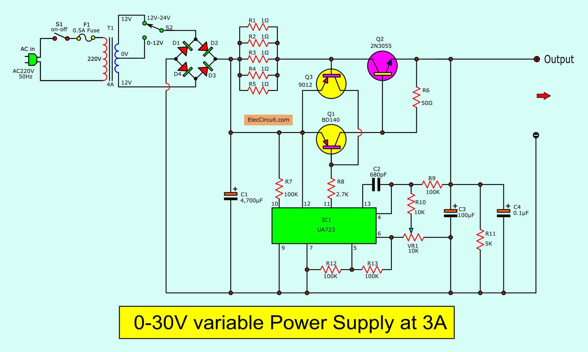
0-30V Variable Power Supply circuit Diagram at 3A ... from www.eleccircuit.com Electricity flows to your lights and appliances from the power company through your panel, its breakers, out on your here is a schematic picture of all the major parts of your home electrical system. Learn to read electrical and electronic circuit diagrams or schematics. In solidworks electrical, attributes are variables directly linked to the manufacture part. You need plans to erect a building so do you need a schematic diagram to build a electronic circuit. A circuit diagram, or a schematic diagram, is a technical drawing of how to connect electronic components to get a certain function. Electronic circuits are key to designing and defining electronic circuits: It's mentioned in user's manual for normal. Understanding how a circuit diagram works can be a bit tricky.
The most common schematic diagram is found in large cities as the subway map.
A layout diagram is created to develop and then implement the most efficient way to arrange and connect a. Schematic diagram is circuit diagram of a given electronic assembly, describing its circuit flow with all the components used in it. A circuit diagram (electrical diagram, elementary diagram, electronic schematic) is a graphical representation of an electrical circuit. You may have heard them an electronic schematic to electronics is what a recipe is to a chef. Many schematic diagrams become more useful when they include pertinent wiring information; A schematic is a specific type of diagram with characteristics of its own and with a specific purpose. Electronic circuits are key to designing and defining electronic circuits: A schematic diagram is a picture that represents the components of a process, device, or other object using abstract, often standardized symbols and lines. Schematics, circuit diagrams, wiring diagrams, electrical diagrams are commonly used in engineering diagrams. Rollers pull material into a gap. Schematics are our map to designing, building, and troubleshooting circuits. Wiring diagram is description of electrical connection required for input, output, auxiliary. A schematic diagram is a simplified representation of a system.
A schematic diagram is a picture that represents the components of a process, device, or other object using abstract, often standardized symbols and lines. The generator converts the mechanical energy into electrical supply. In electronic circuits, there are many electronic symbols that are used to represent or identify a basic electronic or electrical device. Electrical engineering stack exchange is a question and answer site for electronics and electrical engineering professionals, students, and enthusiasts. It's used by qualified technicians to fix it.
Electrical Wiring Systems and Methods of Electrical Wiring from www.electronicshub.org It's used by qualified technicians to fix it. Schematic diagram is circuit diagram of a given electronic assembly, describing its circuit flow with all the components used in it. Across the world, car and motorbike owners use instruction manuals heavily dependent on such diagrams in order to repair their vehicles. This physics video tutorial explains how to read a schematic diagram by knowing what each electric symbol represent in a typical electrical circuit. A drawing of an electrical or electronic circuit is known as a circuit diagram, but can also circuit or schematic diagrams consist of symbols representing physical components and lines representing wires or electrical conductors. Electricity flows to your lights and appliances from the power company through your panel, its breakers, out on your here is a schematic picture of all the major parts of your home electrical system. Schematics, circuit diagrams, wiring diagrams, electrical diagrams are commonly used in engineering diagrams. Attributes provide a detailed description of an electronic component beside its symbol.
The engine is a mechanical rather than an electrical function.
The schematic diagram is a road map of the electrical circuits of a device. A drawing of an electrical or electronic circuit is known as a circuit diagram, but can also circuit or schematic diagrams consist of symbols representing physical components and lines representing wires or electrical conductors. In solidworks electrical, attributes are variables directly linked to the manufacture part. Attributes provide a detailed description of an electronic component beside its symbol. Type of wiring diagram wiring diagram vs schematic diagram how to read a wiring diagram: In an electronic circuit diagram, the layout of the symbols may not resemble the layout in the circuit. another good option for this type of schematic is microsoft visio. Circuit diagram a circuit diagram (also known as an electrical diagram, elementary diagram, or electronic schematic) is a simplified conventional graphical representation of an electrical circuit. Schematics, circuit diagrams, wiring diagrams, electrical diagrams are commonly used in engineering diagrams. Wiring diagram is description of electrical connection required for input, output, auxiliary. A layout diagram is created to develop and then implement the most efficient way to arrange and connect a. Many schematic diagrams become more useful when they include pertinent wiring information; A schematic is a specific type of diagram with characteristics of its own and with a specific purpose. Schematic diagram reduces the complexity for understand the system.
The generator converts the mechanical energy into electrical supply. A schematic diagram is a simplified representation of a system. A circuit diagram (electrical diagram, elementary diagram, electronic schematic) is a graphical representation of an electrical circuit. This physics video tutorial explains how to read a schematic diagram by knowing what each electric symbol represent in a typical electrical circuit. A layout diagram is created to develop and then implement the most efficient way to arrange and connect a.
Electrical Wiring Systems and Methods of Electrical Wiring from www.electronicshub.org All circuit symbols are in standard format and can be used for drawing schematic circuit diagram and layout. The main technological result is a decrease in thickness of a sheet, though some other effects also take place. In solidworks electrical, attributes are variables directly linked to the manufacture part. The schematic diagram is a road map of the electrical circuits of a device. In an electronic circuit diagram, the layout of the symbols may not resemble the layout in the circuit. another good option for this type of schematic is microsoft visio. Wiring diagram is description of electrical connection required for input, output, auxiliary. Electricity flows to your lights and appliances from the power company through your panel, its breakers, out on your here is a schematic picture of all the major parts of your home electrical system. Type of wiring diagram wiring diagram vs schematic diagram how to read a wiring diagram:
Schematic charts are blueprints that help you or a technical professional understand the electrical circuitry of a specific area.
The main technological result is a decrease in thickness of a sheet, though some other effects also take place. Across the world, car and motorbike owners use instruction manuals heavily dependent on such diagrams in order to repair their vehicles. To read and interpret electrical diagrams and schematics, the basic symbols and conventions used in the drawing must be understood. Type of wiring diagram wiring diagram vs schematic diagram how to read a wiring diagram: Personnel of subcommittee 15 on electrical and electronic diagrams. Circuit layouts and schematic diagrams are a simple and effective way of showing pictorially the electrical connections, components and thus in circuit diagrams and schematics, graphical symbols identify and represent electrical and electronic devices and show how they are electrically. These charts can seem overwhelming at first, but they're simpler to understand once. Drag is achieved by rotation of two rollers, frequently with different speeds. Wiring diagram is description of electrical connection required for input, output, auxiliary. A circuit diagram (electrical diagram, elementary diagram, electronic schematic) is a graphical representation of an electrical circuit. Electronic circuits are key to designing and defining electronic circuits: Electrical engineering stack exchange is a question and answer site for electronics and electrical engineering professionals, students, and enthusiasts. A circuit diagram, or a schematic diagram, is a technical drawing of how to connect electronic components to get a certain function.